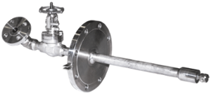

BETE Spillback Hollow Cone Nozzle is a type of whirl nozzle that is equipped with two connections instead of the single inlet found on most whirl nozzles. Unlike standard whirl nozzles, spillback nozzles provides a 10:1 turndown ratio with minimal change in drop size. The spray pattern formed is a hollow cone pattern due to the internal geometry of the nozzle. A basic setup requires a reservoir, pump, spillback valve, and piping to fit up to the nozzle. Spillback nozzles operate on a direct-pressure atomization principle but with a return line feature that allows for a portion of the pumped fluid to be returned to the supply tank. Return line feature utilizes a spillback control valve to vary the amount of fluid returned from the nozzle. This provides high turndown ratios of approximately 10:1. High pressure operation and constant feed pressure allows for fine atomization with relatively little variation in droplet size over the operating flow range of a nozzle
Design Features of BETE Spillback Hollow Cone Nozzles
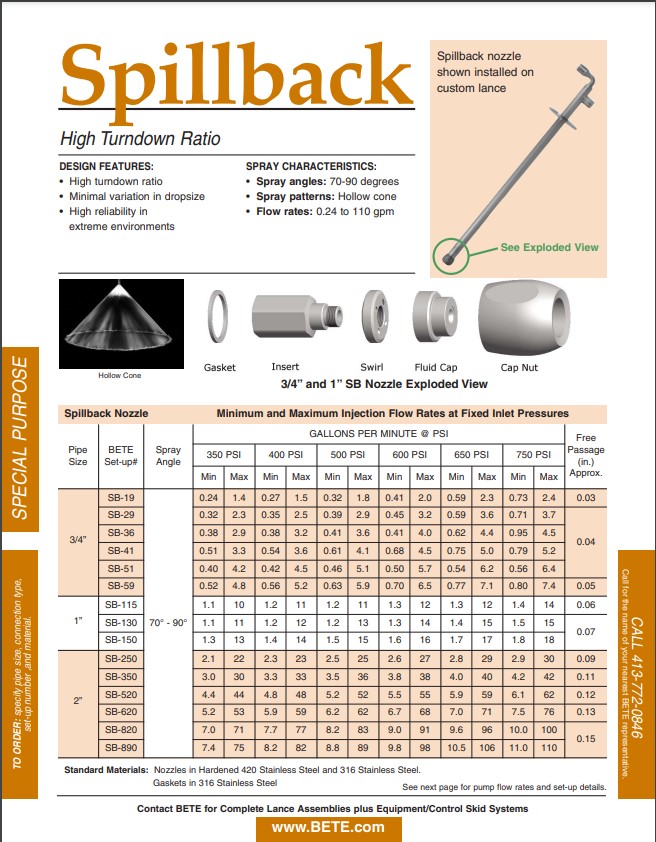
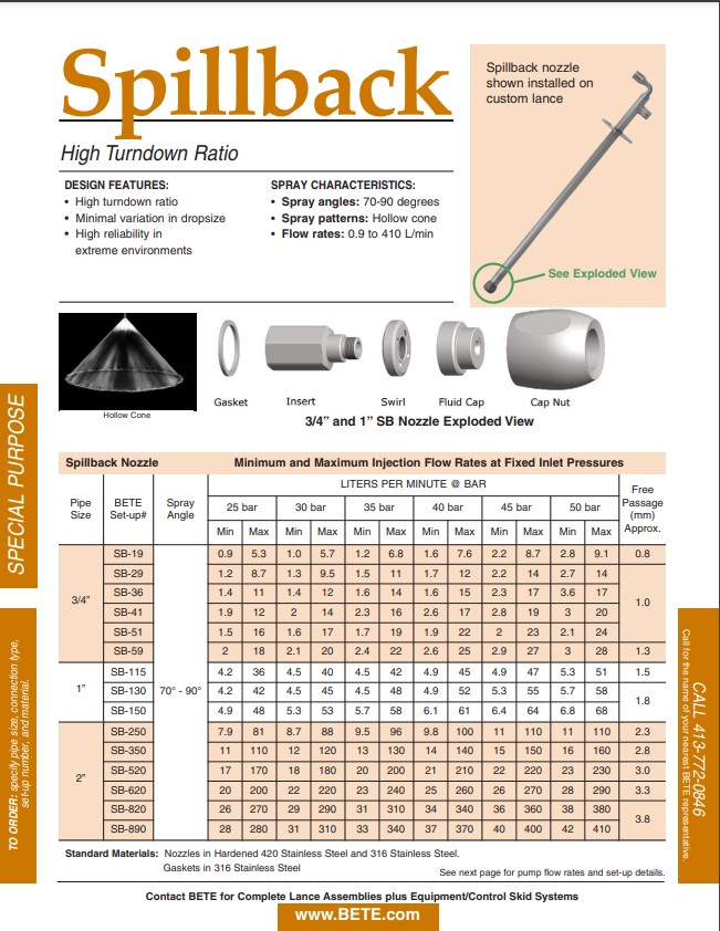
- High turndown ratio
- Minimal variation in dropsize
- High reliability in extreme environments
BETE Spillback Hollow Cone Nozzles Spray Characteristics
- Spray angles: 70-90 degrees
- Spray patterns: Hollow cone
- Flow rates: 0.24 to 110 gpm (0.9 to 410 L/min)
| Available Connection Types | Materials |
| • 3/4”, 1”, and 2” | • Hardened 420SS, 316SS • Gaskets 316SS |
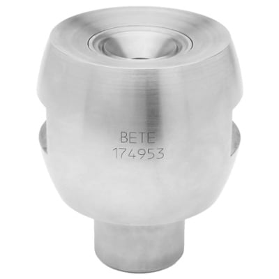
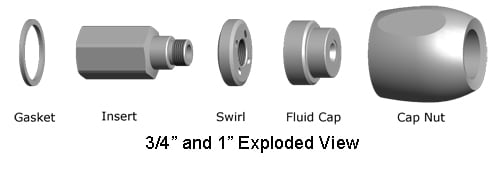
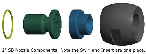
BETE Spillback Nozzle Design
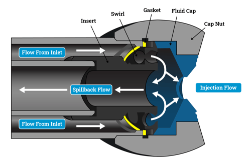
Fluid enters the swirl chamber in the fluid cap through angled holes in the swirl component that impart a tangential velocity to the fluid. As the fluid exits the fluid cap orifice, the tangential velocity creates a cone pattern and atomization of the fluid.
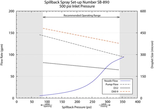
Spillback nozzles achieve a 10:1 turndown ratio of the injection flow rate by diverting a portion of the inlet flow through an internal return line. Return flow is controlled using a spillback valve in the return line to adjust the return flow rate. An increase in flow rate through the return line results in a decrease in injection flow rate through the orifice. A constant supply pressure maintains liquid velocity through the internal swirl disk component, providing relatively constant atomization throughout the flow range.
As the injection flow to the process decreases, the required pump supply flow to the inlet increases. Proper sizing of the pump is critical to operating performance
BETE Spillback Requirements
From process engineering and nozzle selection assistance to implementing automated spraying systems, BETE can customize the system design to fit your operational needs and requirements.
- A basic setup requires a reservoir, pump, spillback valve, and piping to fit up to the nozzle.
- Spillback nozzles operate on a direct-pressure atomization principle but with a return line feature that allows a portion of the pumped fluid to be returned to the supply tank.
- The return line feature utilizes a spillback control valve to vary the amount of fluid returned from the nozzle, which provides high turndown ratios of approximately 10:1.
- High-pressure operation and constant feed pressure allow for fine atomization with relatively little variation in droplet size over the operating flow range of a nozzle.
- NOTE: As the injection flow to the process decreases, the required pump supply flow to the inlet increases.
BETE Spillback Videos